Case Studies
Selected Engineering Case Studies
The following examples are based on previous engineering work in production and industrial automation environments.
Some company-specific, product-specific, and confidential details are intentionally simplified, generalized, or omitted. The purpose of these case studies is not to publish sensitive project data, but to show the type of mechanical design problems I have worked on and the engineering logic behind the solutions.
These examples demonstrate experience with:
- special-purpose machinery,
- rotary indexing machines,
- automated and semi-automatic assembly equipment,
- fixtures and production aids,
- inspection modules,
- leak testing stations,
- retrofit design,
- production-oriented CAD modelling,
- manufacturing drawings and technical documentation.
How to read these case studies
Each case study follows the same structure:
- Project context — what kind of production situation the project belonged to,
- Engineering challenge — what had to be solved from a mechanical design point of view,
- Mechanical design contribution — what type of design work was involved,
- Production relevance — why the solution mattered in a manufacturing environment,
- Deliverables — what kind of engineering output was created.
The examples are written in a simplified portfolio format. They are intended to show engineering thinking, not confidential machine documentation.
Project overview
| Project | Main engineering relevance |
|---|---|
| Rotary Table Assembly Machine | High-volume automated assembly, rotary indexing concept, feeder integration |
| Vision Inspection Module | Camera inspection integration, reject handling, retrofit into existing automation |
| Safety Leak Test Station | Operator-oriented fixture/station design, safety logic, adapter handling |
| Contact Insertion Module | Contact insertion, unwinder integration, retrofit into an existing line |
| Rotary Table Semi-Automatic Machine | Semi-automatic assembly concept, rotary table layout, feeder-supported production |
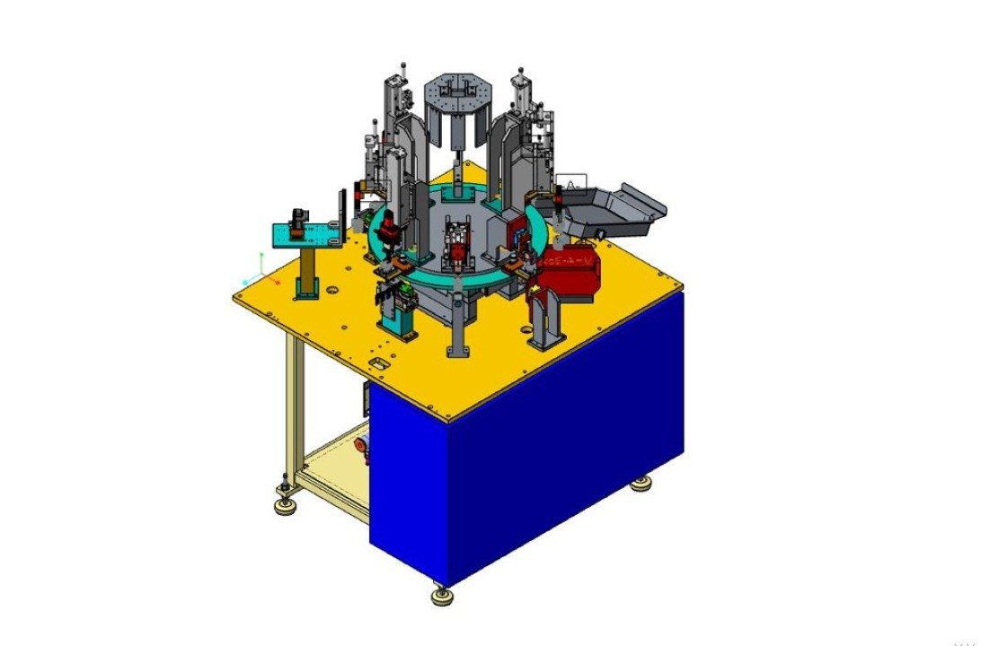
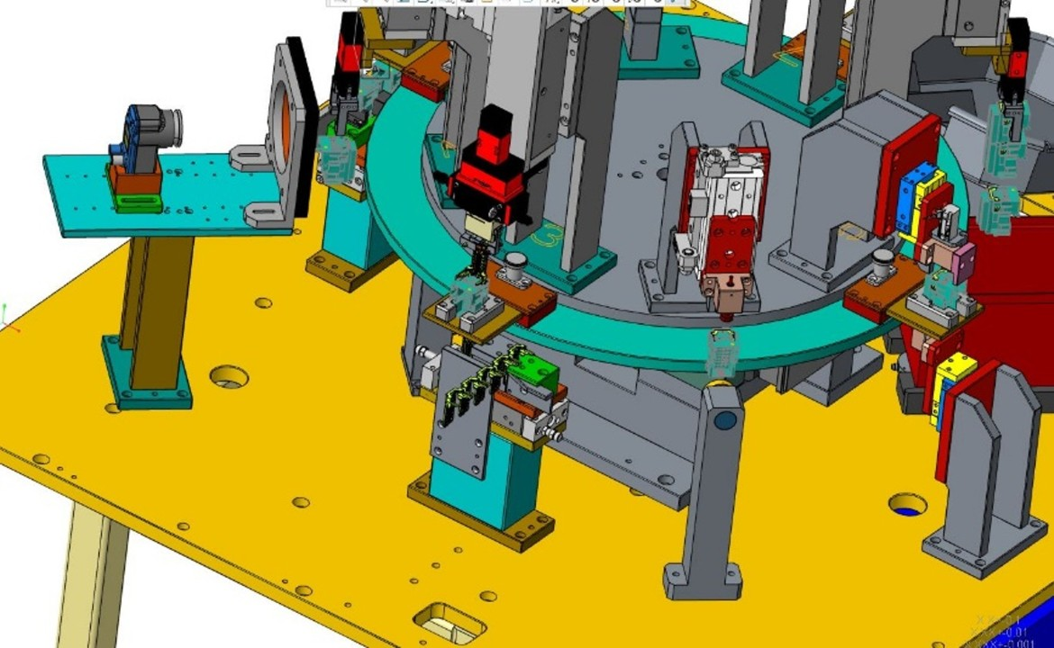
Rotary Table Assembly Machine
Rotary Table Assembly Machine
High-volume automated assembly machine concept using a rotary indexing table and vibratory feeder-based material input.
Project context
The machine was designed for assembling two components in a high-volume manufacturing environment.
The concept used a rotary indexing table to divide the process into multiple stations and vibratory feeders to support automated material input.
Key project data
- Assembly of two components
- Vibratory feeder material input
- Rotary indexing table
- Cycle time: 2.5 s
- Annual production volume: approx. 10 million parts/year
- Operator ratio: 1/1
- Autonomy: approx. 45 min
Engineering challenge
The main challenge was to create a compact, repeatable, station-based machine concept suitable for high-volume production.
The design had to support:
- stable part feeding,
- accurate positioning,
- repeatable assembly,
- station-to-station transfer,
- production reliability,
- maintainability of mechanical modules.
Mechanical design contribution
The mechanical design work focused on the rotary table machine concept and the design of production-oriented station modules.
Typical design considerations included:
- rotary indexing layout,
- feeder integration,
- mechanical positioning,
- assembly station structure,
- accessibility for setup and maintenance,
- robust mechanical interfaces between modules.
Production relevance
At this production volume and cycle time, small mechanical issues can quickly become major production losses.
The engineering value of the design was therefore not only the CAD model itself, but also the creation of a machine concept that supported repeatability, uptime, and stable production operation.
Deliverables
- 3D CAD model
- Machine concept
- Mechanical station design
- Production-oriented design documentation
- Design support for manufacturing and assembly
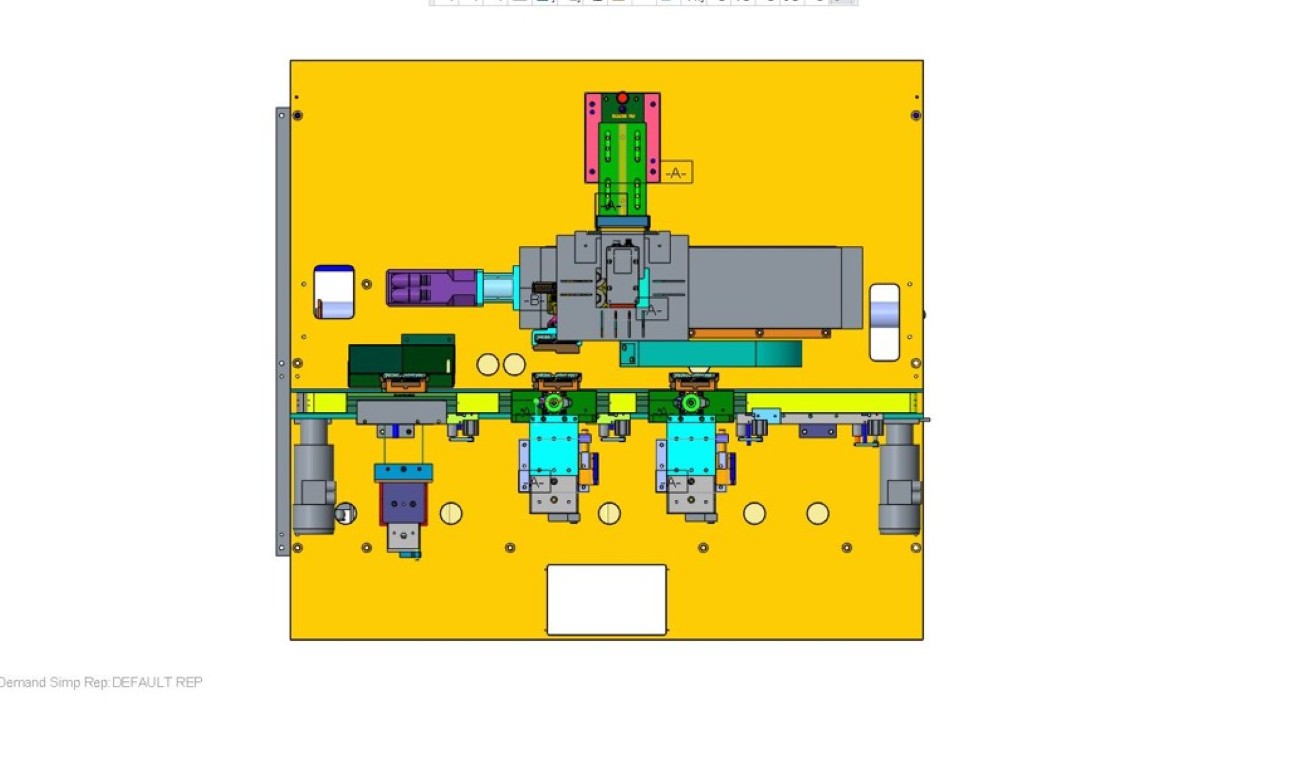
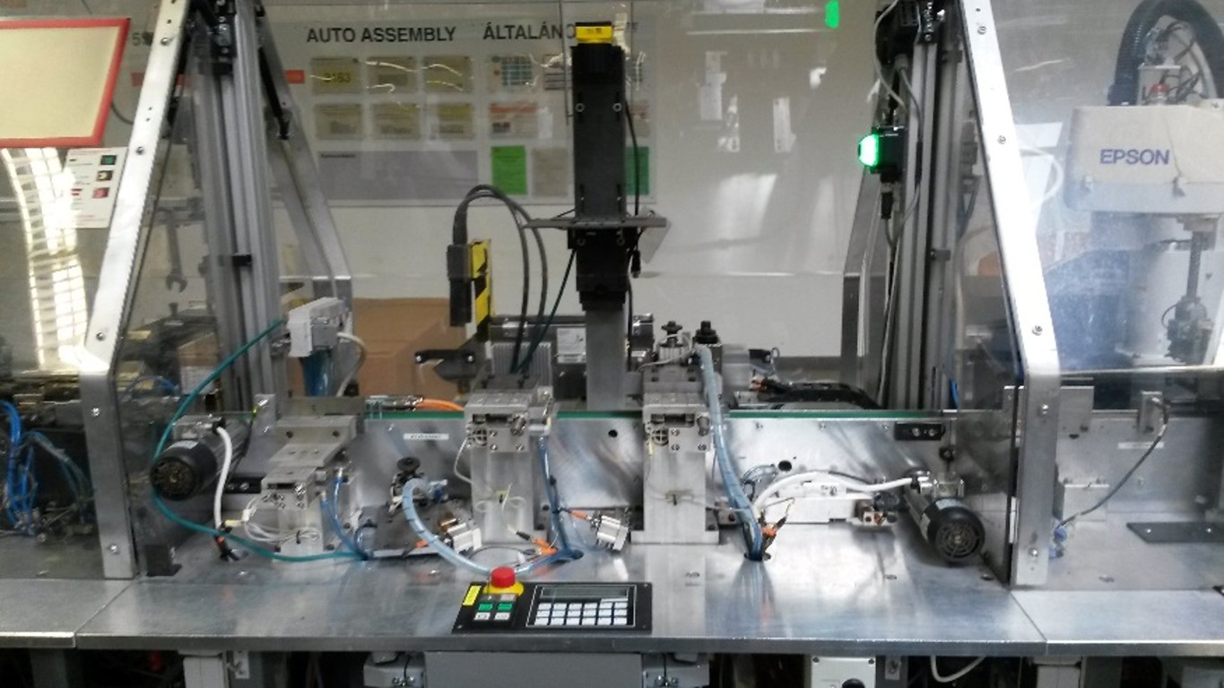
Visual examples
The following images show selected visual examples from the rotary table assembly machine project. Sensitive product-specific and customer-specific details are intentionally not described.
Confidentiality note
Images and detailed machine geometry are not shown here unless simplified or anonymized versions are available.
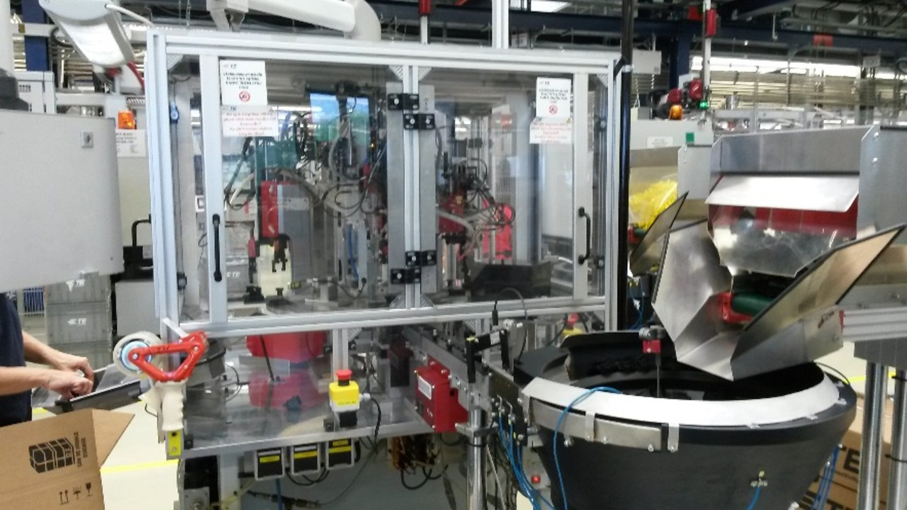
Vision Inspection Module
Vision Inspection Module
Camera-based inspection module integrated into an existing linear automation system.
Project context
The module was developed to check the presence and position of contacts in an automated production process.
It was integrated into an existing linear automation system and supported automatic reject handling.
Key functions
- Camera-based contact presence inspection
- Contact position inspection
- Integration into an existing linear automation system
- Automatic reject handling
- Convertible / removable module concept
Engineering challenge
The main mechanical challenge was not to design a standalone machine, but to integrate a new inspection function into an already existing production system.
This required attention to:
- available space,
- existing machine interfaces,
- camera positioning,
- part visibility,
- reject handling,
- installation and removal,
- production accessibility.
Mechanical design contribution
The design work focused on creating a compact inspection module that could be installed into the existing automation layout.
Important mechanical design aspects included:
- camera and sensor positioning,
- mechanical support structure,
- module mounting concept,
- accessibility for adjustment,
- integration with reject handling,
- layout compatibility with existing equipment.
Production relevance
Inspection modules are often small compared to the full machine, but their effect on production quality can be significant.
A well-integrated inspection module can improve process reliability by detecting missing or incorrectly positioned components before they continue downstream.
Deliverables
- Mechanical module design
- CAD model
- Integration concept
- Production documentation support
- Design notes for installation and manufacturing
Visual examples
The following images show selected visual examples from the rotary table assembly machine project. Sensitive product-specific and customer-specific details are intentionally not described.
Confidentiality note
The case study is intentionally simplified and does not include customer-specific product or machine details.
Safety Leak Test Station
Safety Leak Test Station
Manual / semi-automatic leak testing station designed for safe and flexible adapter handling.
Project context
The station was designed to receive multiple leak test adapters without requiring pneumatic connection of the adapters.
The concept supported both right-handed and left-handed operators and included safety-related functions to reduce the risk of incorrect operation.
Key functions
- Compatibility with multiple leak test adapters
- No pneumatic connection required for adapters
- Usable by right-handed and left-handed operators
- Operation allowed only with adapter installed
- Rejected part fixation
- Safety-oriented leak testing workflow
Engineering challenge
The key challenge was to design a practical production station that supported flexibility, operator usability, and safe operation.
The design had to consider:
- adapter interchangeability,
- operator ergonomics,
- mistake prevention,
- rejected part handling,
- clear mechanical interfaces,
- safe and simple operation.
Mechanical design contribution
The mechanical design focused on the station structure, adapter handling concept, and operator-facing fixture layout.
Important design aspects included:
- adapter positioning,
- mechanical support and fixation,
- safe handling logic,
- ergonomic access,
- left-hand / right-hand usability,
- fixture layout for production use.
Production relevance
Leak testing stations are quality-critical process points.
A poorly designed station can create operator errors, unclear workflows, or unreliable test preparation. The value of the mechanical design was to support a safer, clearer, and more production-friendly leak testing process.
Deliverables
- Fixture / station CAD model
- Mechanical concept
- Production drawings
- Design documentation
- DFM and usability considerations
Confidentiality note
The project is described without customer-specific product geometry or internal process details.
Contact Insertion Module
Contact Insertion Module
Contact insertion station with unwinder, integrated into an existing linear automation system.
Project context
The module was developed to support a new product variant on an existing production line.
It included contact insertion functionality and material unwinding, while fitting into the constraints of an existing automation system.
Key functions
- Contact insertion station
- Unwinder integration
- Installation into an existing linear automation system
- Support for new product introduction
- Production line modification
Engineering challenge
The main challenge was retrofit design: adding new functionality to an existing line without treating the machine as a blank-sheet design.
This required attention to:
- existing machine layout,
- available space,
- mechanical interfaces,
- material feeding,
- insertion process support,
- production integration constraints.
Mechanical design contribution
The design work focused on the mechanical station concept, unwinder integration, and layout compatibility with the existing automation system.
Key design aspects included:
- insertion module layout,
- material feed path,
- unwinder support,
- mechanical mounting,
- integration with the existing line,
- documentation for manufacturing and installation.
Production relevance
New product variants often require practical modifications to existing production equipment.
The engineering value in this type of work is the ability to adapt existing automation without overcomplicating the machine or creating unnecessary production risk.
Deliverables
- CAD model
- Mechanical station design
- Integration concept
- Production documentation support
- Design notes
Confidentiality note
The project description is generalized to avoid sharing product-specific or customer-specific information.
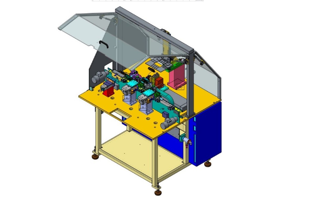
Rotary Table Semi-Automatic Machine
Rotary Table Semi-Automatic Machine
Semi-automatic rotary table assembly machine concept for five-component assembly.
Project context
The machine concept supported the assembly of five components using vibratory feeder-based part feeding and operator pre-assembly.
The project was in the design phase.
Key project data
- Five-component assembly
- Vibratory feeder material input
- Operator pre-assembly
- Rotary table concept
- Cycle time: 6.2 s
- Annual production volume: approx. 4.5 million parts/year
- Operator ratio: 1/1
- Autonomy: approx. 45 min
- Project phase: design phase
Engineering challenge
The main challenge was to combine manual pre-assembly with feeder-supported semi-automatic machine operation.
The design had to support:
- operator-machine interaction,
- part feeding,
- rotary table process flow,
- assembly station logic,
- cycle time requirements,
- practical access for production and maintenance.
Mechanical design contribution
The design work focused on the machine concept and the mechanical layout of the rotary table assembly process.
Important design considerations included:
- rotary table layout,
- feeder integration,
- operator loading / pre-assembly area,
- station arrangement,
- production flow,
- mechanical accessibility,
- assembly process planning.
Production relevance
Semi-automatic machines often require a careful balance between automation and operator involvement.
The engineering value of the concept was to support production output while keeping the process understandable, maintainable, and suitable for operator interaction.
Deliverables
- Machine concept
- 3D CAD model
- Station layout
- Mechanical design documentation
- DFM and assembly considerations
Confidentiality note
The description is simplified and does not include confidential product or customer-specific details.